Not all the gpio’s are set “high” or “low” some may be floating this is why you should use pull up/down resistors.
That said…If you can find which are normally high after boot, then you can get away with using those without a pullup resistor. But it is advisable when pulling them low ( ie when switched) to do this through a resistor to prevent the risk of overloading the port and damaging your kit.
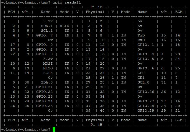
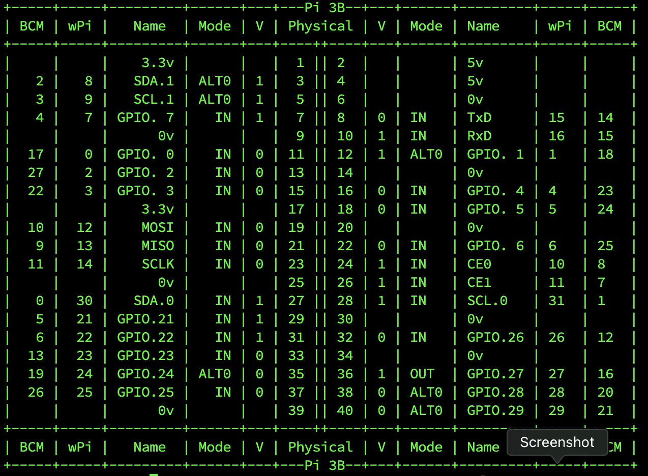
You can find out which way your ports are set by SSHing into the pi and doing a gpio readall
that will give you a nice little chart showing you which state your ports are set.
bare in mind though if you are using a pi 4 you’ll need to update to be able to read the ports
cd /tmp
wget https://project-downloads.drogon.net/wiringpi-latest.deb
sudo dpkg -i wiringpi-latest.deb
Also bare in mind that you will also need 100nf capacitors across all the switches otherwise they will be as erratic as an erratic thing.
wanted to verify this and try to install the plugin from the store. But obviously they changed the package.json during the merge, to no longer support v3.179. Unfortunately I did not just change the package.json but tried to install the latest version, which ended in a mess with my WiFi dongle.
Will have to re-setup my development system and downgrad to an older version first, to fix the WiFi problem that exists with 3.251.
Probably wont have the time to look into it before Easter again - so please be a little patient.
Not sure, what the problem might be. I am basically relying on onoff for the pushbuttons. Need to have a look myself. On my V3.1x system it worked with the version from my local Repo
Just to clarify, I have V3.251 clean install and installed your rotary encoder 2 plugin 1.0.11 from the store.
I am only using one encoder but it all works fine and as expected, no erattic behaviour, button works every time too.
Hi, did not have time to bring my test-system back up yet - seems to be a bigger issue with the WiFi dongle and the last working version is not available anymore and even 3.198 is not working anymore. Need to dig some further.
However I looked at your log and at my code. The code is just creating an instance of the GPIO object from onoff per button and then setting up a watch callback that reacts on the rising and falling edges of the GPIO. Depending on the active-high/active-low setting, a button press is either a rising/falling edge and a release is the opposite.
Normally, rising and falling edge will always alternate, but the log shows 5 button presses in a row and afterwards 5 releases in a row (I assume, you did not press 5 times within 1 second). As the message says, this is not normal and may have different reasons:
bouncy button (if the spikes are faster than the reaction time of onoff, but I remember, you had hardware debouncing, right?)
node being too busy with other things to react fast enough
race conditions in my code, which I did not observe during testing
debounce time and long-press, double-press time are not matching
The first item should be solvable by increasing the setting for the debounce-time (e.g. 50 or 100ms), the log tells us, that the releases seem to be detected after ~200ms, so the 5 presses seem to come within under 200ms, i.e. at 40ms intervals.
The second and third might be the case, if the current versions of Volumio are running things differently from the Beta I tested with (can only verify once I fix my test system).
The fourth item you can try by yourself (or at least post your settings here). If you are not actively debouncing, you need to set at least 50ms of debounce time and the double-click and long-press times should be significantly longer (at least factor 2 better 4, I’d suppose).
Generally, JS seems not perfect for real-time applications. If the processing of button events is stuck in the Node eventLoop, it may lead to strange behavior.
If it turns out, that onoff is really too slow for the button now, a possible solution would be to abondon onoff and move to a similar approach as for the rotation (using Kernel dtoverlays). But so far I sticked with the easier implementation, because the button events seemed slow enough. Need to ask for some more patience until after the Holidays until I can look into this.
I can confirm I have hardware debouncing on the switch. The very same setup was working fine with v1.0.7, as soon as I updated to 1.0.11 the buttons did not work anymore.
Increasing the debouncing time up to 200ms does not solve the problem.
Hi!
Looked at the code a bit more. I suspect that this is a timing issue due to the added functionality with the double-press.
I suspect that it is unstable depending on the system loading/ node eventLoop. That might explain, why it is not observed by everybody and did not show up when I tested it.
I have my test system up again and luckily it shows the same behavior, while my main system works.
Will give it some thought how to modify the implementation. But can only start to test it next week.
Sorry for the inconvenience!
@Whisper74
Its not just the ALT0 for you to use, the ALT0 have more than likely been set by your dac. You cannot use those as obviously are being used by your dac.
In the gpio readall chart
Mode. alt = alternative, in = input, out = output
V, 1=high 0=low or floating.
Physical are the physical pins on your rpi header
BCM (Broadcom) are GPIO numbers you enter into the software correlating to the physical pin you have used.
To use them without pull up/down restistor you are better off to choose one that is set high.
So you need to find one that says IN and 1 ie an input that has internal pull up already set.
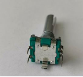
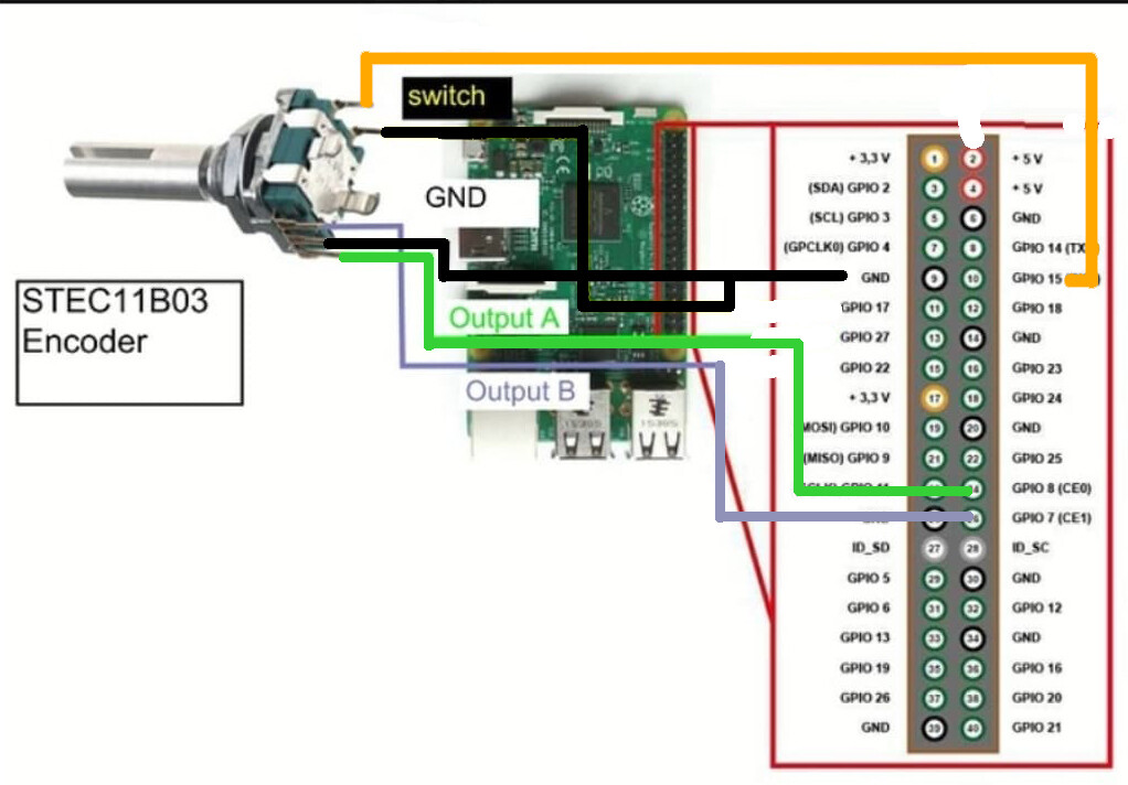
The way I have my encoder wired.
Center pin of the group of 3 connected to 0v, left pin to gpio 7 (physical pin 26) right pin to gpio 8 (physical pin 24)
then the other side with just 2 pins, one connected to 0v and the other connected to gpio15 (physical pin 10)
All connections to the gpio go through a 1K resistor and also have 100nf capacitor between 0v and the gpio ( switch side)
The 1 K resistors are only there for current limiting to protect the gpio port, and the capacitors are there for debouncing ( ie prevent acidental double clicking)
when connecting the rest of your encoders ensure that you are not using any gpio’s that your dac is using. A quote from hifiberry
HiFiBerry DAC2 HD
GPIO2-3 (pins 3 and 5) are used by our products for configuration of the DAC and the clock circuit. GPIOs 18-21 (pins 12, 35, 38 and 40) are used for the sound interface. GPIO16 is used internally to reset the DAC. You can’t use these GPIOs for any other purpose.
mmm… i ve unite all 3 positive encoder pin and soldered to 3v
… now i have a doubt
… i ve done the same thing to gnd cable (3 merged together and soldered to 1 gnd pin)…
do i have to separate to 3 single negative encoder pin to enable the press button with combination 0v - gpio?
That in theory should work.
But as above its not working in some configurations.
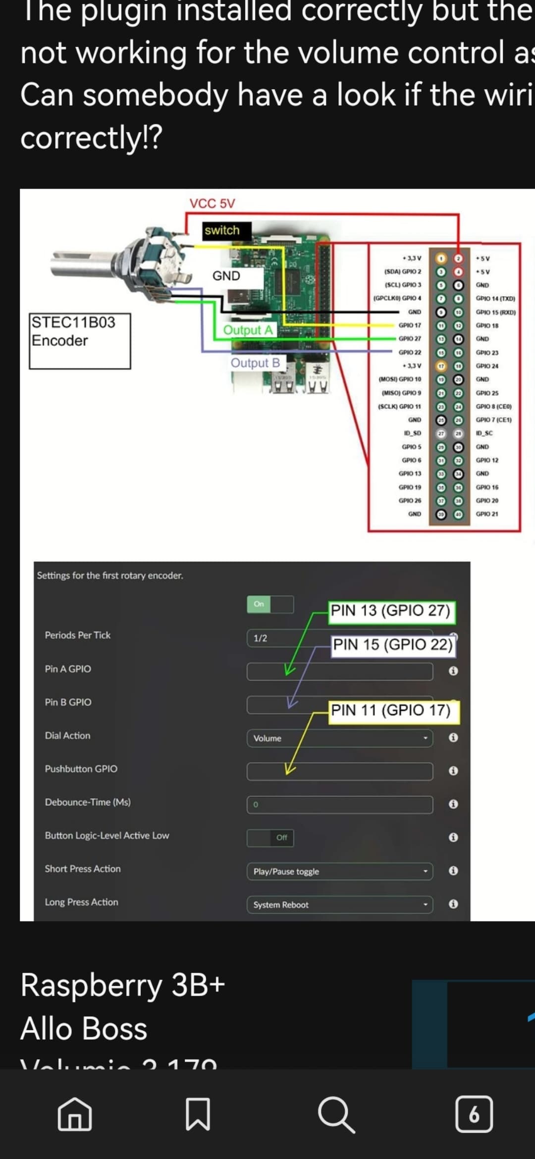
Heres a diagram of how mine is configured there is also 1k resistors in line with the GPIO ports and 100nf capacitors conected between all the GPIO ports and ground (switch side)
This works fine for me on a RPI 4, Volumio 3.251, and Rotary plugin 1.0.11