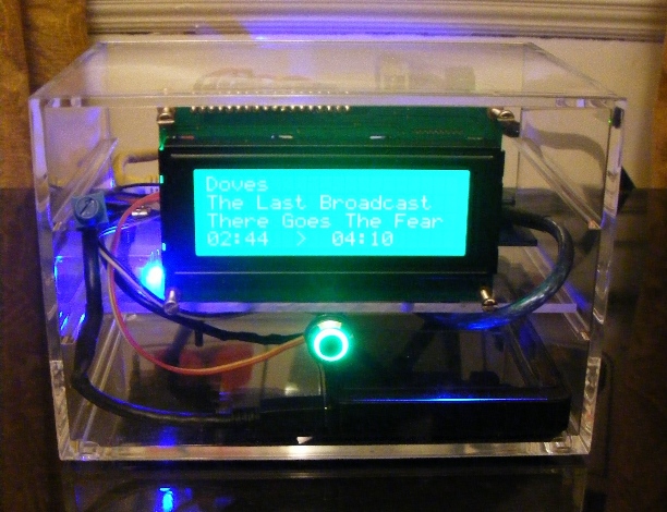
Just thought I would share some pictures of my finished build…
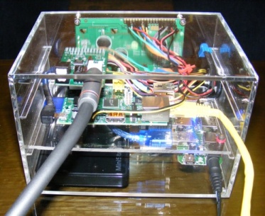
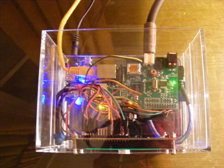
This is a Rev 2 Pi running Volumio 1.5 and LCDproc to drive the 20x4 Adafruit HD44780 RGB LCD screen. My library consists of around 500 FLAC albums, stored locally on the 1TB Buffalo Ministation USB Drive, sitting at the bottom of the case alongside a stripped powered USB hub. It was all such a tight fit I even had to strip off cable connectors! The Pi has a Hifiberry Digi digital output board on a riser ( sound quality and noise floor are dramatically improved compared to over USB) connected by SPDIF to an Emotiva XDA1 DAC and out to my Copland CTA501 tube power amp. The power switch (soft reset) on the front of the case is connected to the Pi’s P6 header and 3.3v on the GPIO. Play control is via MPDroid on Sony Xperia Z Ultra.
After many hours of tinkering I think I have finally found a stable working setup for my media library!
One thing eludes me though… with the AndyPi LCDproc display script I’m using, if no track is playing, the screen shows nothing but an empty track timer on line 4. I would prefer the LCD to show something like:-
“My text”
“IP Address”
“Date”
“Time”
when ‘mpc_status is stopped’. My coding skills are poor, and despite much research, I have been unable to accomplish this.
Does anyone know how to do this? Help would be appreciated!
I followed the instructions at andypi.co.uk/?p=334 then I had to modify LCDd.conf slightly under the driver section for Hitachi HD44780 to match the GPIO pin allocation. (The BL is irrelevant). Extract below:-
Specifies the size of the LCD.
In case of multiple combined displays, this should be the total size.
Size=20x4
D7=14
D6=23
D5=24
D4=25
RS=7
EN=8
BL=18
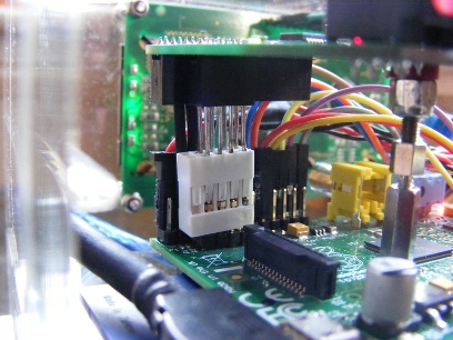
I made a “riser” out of an old PC 10 pin connector and connected the Digi on that into the Pi’s P5 header which raised the Digi sufficiently (about 1cm). I carefully unclipped and retracted the cables and female metal pins from the white connector, pulled out the cables and soldered (8) short lengths of paperclip onto the female pins and reinserted them into the white connector. I made two slightly longer pins (in pic - covered in black heatshrink) again soldering the two spare female pins on one end of each, and they connect to the Pi’s GPIO. (These are the only two pins that the Digi needs from the Pi’s GPIO).
So the Digi is now fully connected, but hovering above the Pi’s GPIO block - so not interfering with the Dupont cables installed in the Pi’s GPIO block from the LCD. There was quite a pull on the Digi from my connected heavyweight SPDIF cable, so for stability, you can see in the picture that I bolted the Digi onto the Pi’s mounting holes with old motherboard risers.
A bit of a Heath Robinson solution, but with my OCD issues and tendency to over-engineer things, it was the obvious solution