Thanks for the tip for the labels! I’ll look into that.
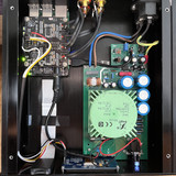
About the cables I’m aware of this issue and I’m still planing to improve that. Currently I positioned the cables to have as much space as possible between them which might not be well visible in the pictures. While the main power leads run close to the bottom plate the signal leads for the RCAs run close to the top plate so there is some room in between. I initially wanted to arrange the PCBs differently inside the case to avoid such cross cabling issues but the space didn’t allow it. Maybe I can improve that when replacing the wires. I unfortunately didn’t have shielded ones near so I used those instead. Thanks for the reminder though!
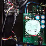
Do the hats require separate power or are they powered from the pi? Does the PSU offer dual supplies? (Its kind of hard to make out the specs on the transformer.) Did you consider a switched power supply at all?
@DannyBoyNYC: Thank you! The hats do not require separate power but you can provide power to the KALI reclocker hat to exclude influences from the RPI by changing a jumper on the board.
You can find the specs of the power supply here https://www.audiophonics.fr/en/hifi-power-supply/audiophonics-lpsu25-linear-regulated-low-noise-power-supply-usb-115v-to-5v-2a-25va-p-12581.html
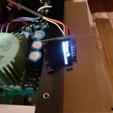
The transformer seems to have two outputs at 7.5V/12.5VA and the power supply has 3 outputs in total (originally 2 USB and 1 Jack) which seem to be filtered with individual capacitors but I don’t have more details than that. I first had a very simple switched power supply and then upgraded to this one which seemed to provide a slight subjective improvement to the sound.
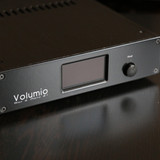
@noire: Thank you! I indeed wanted a simple setup as it fits the rest of my equipment. A small LCD is something I indeed considered but I wasn’t sure whether it would be possible with the KALI + Piano DAC and the little number of GPIO pins you have left to use. Maybe I’ll dig a little deeper into that to see if it’s doable and then I can redesign the front panel with one. It would be a great feature!
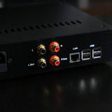
I’ll replace the front plate with a frosted acrylic one until I get access to a milling machine to cut the aluminium. There’s just enough space on the back for network socket, power connector & RCA’s
The dimensions are given in wide x height x length, for example I want one with height 50mm , for those the wide is only 20 mm.?
What size do you have exactly? I want to make an ideea
Thanks
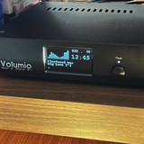
I only seem to have a partial success. After rebooting Volumio the display indeed turns on but only shows the volume bar like in the picture below.
In addition, if I change the volume on the UI it doesn’t seem to be updated on the display. I didn’t modify the pages_ssd1306.py file yet as it seems to have a standard set of widgets already in place.
Is there anything I missed and someone could help me getting fixed please?
Thanks, Andrew! With the install commands to use Saiyato’s pydPiper plugin and after adjusting the ExecStart command to the following at /data/plugins/accessory/pydpiper/unit/pydpiper.service it worked instantly!
Now I only need to find a way to get a clean rectangle cutout at the front panel for the display.without a milling machine but then my project shall be finished. Thanks for your help!
Assuming you use facebook, post a status asking if anyone has access to a milling machine, you may find a friend of a friend can do it for you - worked for me - or will work when the case arrives
With the tip of andrewnorth for the plug labels at the back I came to scale model decals which you apply with water. You can get sets of individual letters which I used. It’s a bit tedious to get the letters all in line but the result is great.
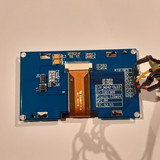
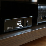
After playing around a little bit with the 0.96" display I rather found it too small to read from the couch or near it as the system is standing on a lower shelf under the TV. I started looking at the 2.42" OLEDs. They obviously use a different driver (SSD1309) however seem to be compatible with SSD1306 so I ordered on from AZDelivery. At many of those you seem to have to move a resistor (R4 to R3) and bridge a contact (R5) at the PCB in order to make it work with I2C. So I gave it a try but the display remained black and with the i2cdetect command I couldn’t find its address either.
Eventually I found a German community where someone pointed out the specialities with these OLEDs and that the RES pin has to be connected as well in order to make it work. Since there doesn’t seem to be a way to control the RES pin on the RPI easily he seems to have found a different solution.
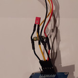
He used a 18kOhm resistor between VCC and RES and a 47nF foil capacitor (must be foil) between GND and RES. His statement was that the RES pin must be first connected to GND and then to VCC which he realized with this wiring.
I thought I’d give it try. What else shall I do? And see there it works! The only thing I had to adapt in the pydPiper page file was the volume change bar. The size seems to have caused the image to flicker which I could solve by just shrinking it by some pixels. I have no explanation for this. The rest works fine.
With the new display I of course also needed a new solution for the front panel. Since I already drilled holes into the old panel for the LEDs I rather wanted to replace it with a new one without so many LEDs and the OLED in the center instead. Somewhere in a thread here I stumbled upon https://www.schaeffer-ag.de/ who can produce front panels by your needs if you create the 3D model with their software. A bit pricy for a single panel but the quality is perfect, it has colored engravings and I’m quite happy how it ended up.
So it’s time for another update on this one. Not only that I had to re-upload all the images since the previous hoster closed but also due to some minor modifications.
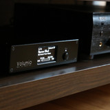
I stayed with Volumio version 2 quite long as I had a try with v3 before but couldn’t get pydPiper reliably to work. Now I had another try and went with MPD_OLED instead. There was some trial and error related to it since I use an SSD1309 display. Whoever is interested can read from here:
The switch to MPD_OLED also allowed me to rewire the display as the plugin also supports a reset pin. The previous solution with the capacitor and resistor worked quite well but not fully stable. In some rare cases the display would crash with a static white noise image as soon I powered it on. I would have to power it off, wait a couple of minutes and then turn it back on. With the reset pin managed by MPD_OLED this didn’t happen so far.
I also got a micro SD extension cable that easily allows me access to the card. Before I had to change it with some pliers as Kali is bigger than the Pi on that side so you couldn’t reach the card with your fingers.
Now I’m up to date again!
(The display is actually white but the camera turned it blue)