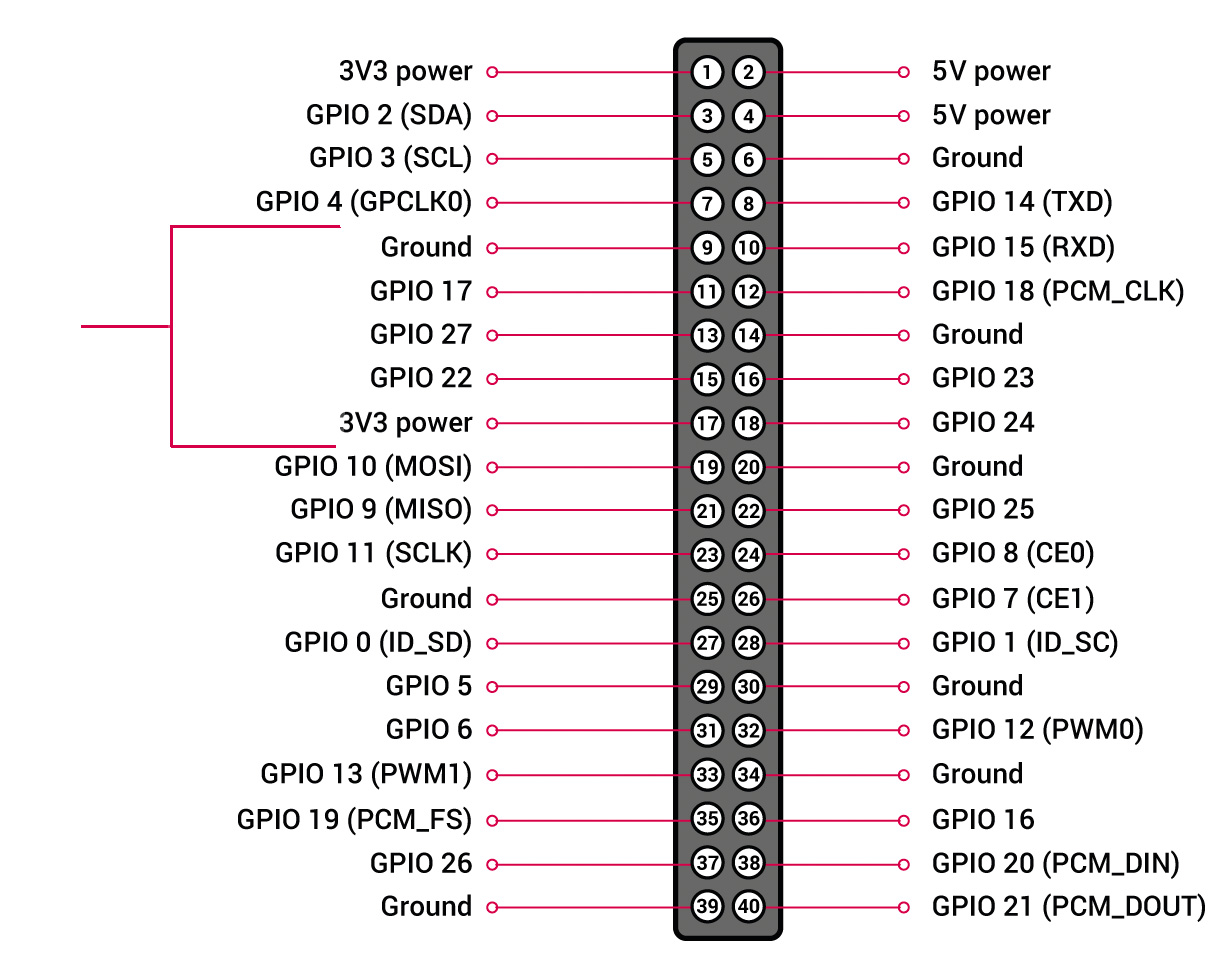
There should be at least one, and possibly two more connection pins for your encoder. The bracket that you’ve shown includes both Ground and 3v3 - it’s important to know which of those pins are connected to what.
As for the GPIO pins that you’re using, they all default to being inputs with a low pulldown (at least according to https://raspberrypi.stackexchange.com/a/51480/122547). This means that your switch and rotary encoder would both need to be “active high” and wired to 3V3 (not ground).
If you prefer to run “active low” for the switch and encoder then you can change the GPIO assignments by editing /boot/userconfig.txt to set up the GPIO pins, for example I use:
to set the pins I use to be input (ip) with a pull up (pu) so they default to logic high and get pulled to logic low using ground on pins 39 and 34.
As an aside, I don’t know whether your rotary encoder has any current limiting resistors, but I recommend adding a 1kΩ or similar in series with the common terminal and the switch to prevent damage in the case where a GPIO pin gets accidentally set to output and is shorted.