So I spend a solid hour with a multimeter first making sure the cable I made works then trying to figure out if my questionable soldering skills are the issue. The problem is soldering these tiny pins to the tiny board is just beyond me. Maybe it’s right, maybe it isn’t. I can’t believe they expect kids to do a competent job soldering these. I’m getting voltage across the various pins at the board end of the cable, so maybe it’s ok. But it isn’t worth saving $13+shipping to mess around with it anymore.
So, while I wait for the mail to deliver my new pi WH (with pre-soldered board), does anyone have any troubleshooting tips to see if this is even my problem?
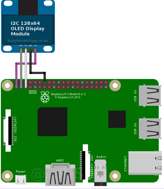
Ok, now you have me concerned. I’m supposed to be soldering on resistors? I thought the thing I bought was ready to connect directly to my GPIO? It has Vcc, Gnd, SCL and SDA connections, and seemed the same as what you used in your Readme. What am I missing here? Where do the resistors go?
Darmur, I don’t think pushing a $50 hat on my (poorly) soldered $10 pi zero GPIO will help anything. Sound works fine out of my USB DAC. I was trying to add a tiny display.
Matt, I think people are genuinely trying to help you here. Whether you are accomplished at soldering or not is down to you. If not, then go down the ready-made route.
I understand that and appreciate the help. As I mentioned in my original post, I’ve ordered a pre-soldered pi zero. I was just wondering if there is any troubleshooting I could do while I wait, for instance to see if it’s really my soldering that’s the problem or if I have a bad OLED module.
I suspect, based on nothing other than how easy it is to short circuit adjacent pins on a small header, that it is soldering, but hang on for your new pi zero … it won’t be long. Then you’ll have the answer to your question ;). It’s all a learning curve, and my soldering skills are pretty rubbish too
Looking at the specs, you don’t need to do solder any resistors as it has the SSD1306 driver included.
Just the 4 wires, should do the trick.
Just make sure they didn’t twist the SDA and SCL.
So you can try by swapping them. It won’t hurt the Pi or OLED.
I had the same issue, but installing the plugin MPD-OLED did the trick.
Also check if you have not more than 1 I2C port enabled. With the commands
sudo i2cdetect -y 0
sudo i2cdetect -y 1
sudo i2cdetect -y 2
sudo i2cdetect -y 3
The OLED address is most likely “3C”
Ok, I have my new pi zero wh, with pre-soldered pins. And scanning still turns up nothing. I even ditched the cable I made and directly jumpered the pins to the OLED. Nothing. Here’s the error I’m getting in case anyone has ideas:
No devices were found on I2C bus /dev/i2c-0 because it appears to be disabled.
Devices found on I2C bus undefined were:
None
Also the i2cdetect is still showing blank (for 1. for 0,2,3 I get an error)
The OLED may be defective (they are fragile), but if you soldered the header on that then you could check the soldering carefully with a magnifying glass (although I imagine you have already done this). Also, maybe the display is not what it was advertised as. Perhaps you could post a photo of the back of it for comparison with other models.
I don’t know what generated the message about the I2C bus, but it refers to bus 0, when bus 1 is the correct bus to use (but specifying bus 1 will not help until you can see your device with i2cdetect -y 1).
Long version: I used another SD chip with a regular pi os on it to try to figure out how to use the OLED to test it. Hit a dozen walls until I finally figured out you need to change your config.txt to allow i2c. Got it working so I knew my OLED itself wasn’t broken. Popped back in my SD card with volumio on it to start debugging… and i2cdetect worked.
So was it just I hadn’t rebooted before? I have no memory of whether I did, though it seems like I would have unplugged and plugged back in my pi several times during testing. Or maybe just a loose wire? Seems unlikely. Anyway, works fine now.