The code over e-mail should be fine.
Regarding DSD, as I mentioned already in our conversation I don’t know how to fix that at the moment. Let’s hope that when more people will start using the meter/plugin somebody will suggest the solution.
To simplify a little bit the soldering work you can use a resistor network. Here is the example:
In that network one side of resistors connected together and has a separate pin. For 12 LEDs you can use 2 networks with 6 resistors. They have 7 pins where one pin is a common one.
Currently I use a 1.3 inch lcd display, a power up button that uses sda pin (gpio3). Shutdown button I have configured with volumio plugin on another gpio pin because gpio3 is used for lcd setup.
Can I add in this setup also the led vumeter?
I guess I that I2C needs to be on 3 different buss adresses, first for lcd, second for first led array and third for the second led array.
Am I wrong?
Will I be able to use the sda as a wake up if I will add the vumeter and the lcd display 1.3 inch?
I see that you have a power button. How do you configure it? It’s wake and shutdown the volumio, if yes what pins have you used because you use?
I also saw in the picture that you have a quarantine plugin in volumio, do you plan to make it public in volumio?
Thanks.
Lintbf, I can answer your I2C questions. I2C allows connection of the multiple devices. Each I2C device should have the individual address. If you have I2C LCD with one address then you need to use two other different I2C addresses one for the Left VU Meter channel and the other for the Right VU Meter channel. If you use the module MCP23017 you can change the I2C address using pins A0-A2. I2C devices connected to the same SDA and SCK lines don’t conflict with each other if they use different addresses.
If your wake up button works fine with LCD, I think it should work with VU Meters as well. Though I would separate all parts.
sleep : I am using remote control sending signal to shutoff the display or after some time that the player is not playing (I used 5v relay with gpi out to shutoff the HDMI display) while all process are running
when status changs back to play I wake up the display
shutdown Volumio with another click on the remote using to software os shutdown
3 “Hard” shutoff I am using 12 v trigger relay from my external dac . so when power on/off the dac , my player power/on/off
Hello,
Thanks for the explanations.
How do you handle for example a new volumio sw versions and what ro update the curent one, you need to start the whole chain of configuration?
What will be the best approach in that case of multiple devices connected to rpi.
Thanks
oh good question, I had to make some hacks inside some of the Volumio configuration files (IR,DAC etc)
but than I realised that Volumio make an integrity check before trying to update from it’s web UI. so it fails to update. but, I can make force update from ssh by using a command, and it worked for the last 3 updates without any problem and now I am running the last version. any way before doing update I always make full backup for the sd card image.
I see that you use 2 regular psu switchable for the hdmi and hdd. I am plan to use a meanwell 15w module. What module do you use?
Do you think that 15w will be enough for hdmi 3.5 inch, and rpi
What buttons have you used on right side. are really nice, if you have a link…
The design of the case you have done it in a tool?
Sory for the high number of questions but your project is so complete. I just ordered the led arrays.
1 if you aren’t plan yo use hdd, than 15w should be enough also for the display,
but if not you can always add a simple cell phone psu only for the display.
2 https://www.aliexpress.com/item/32949015301.html?spm=a2g0s.9042311.0.0.27424c4dtDnvZY
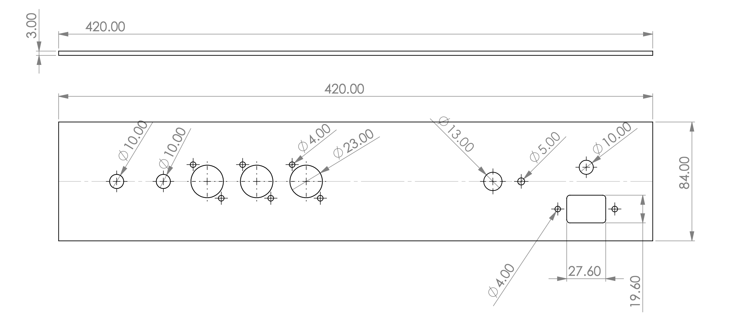
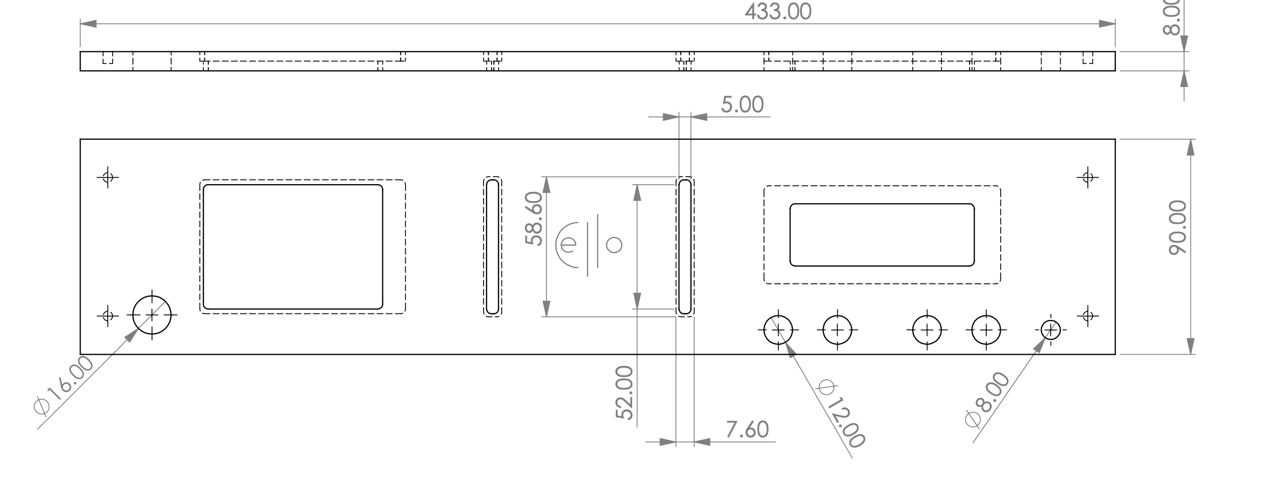
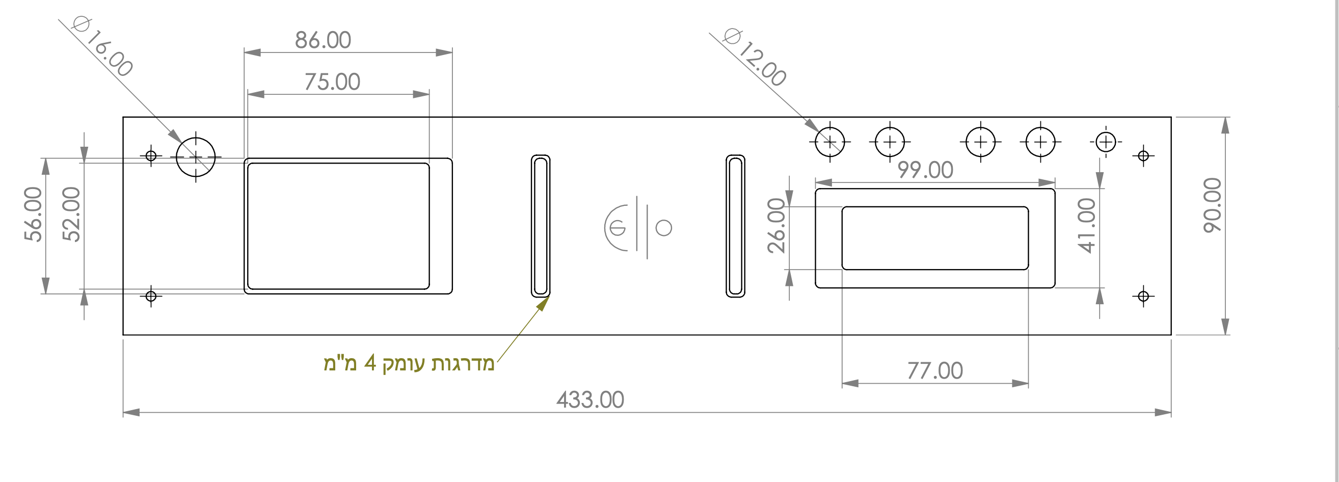
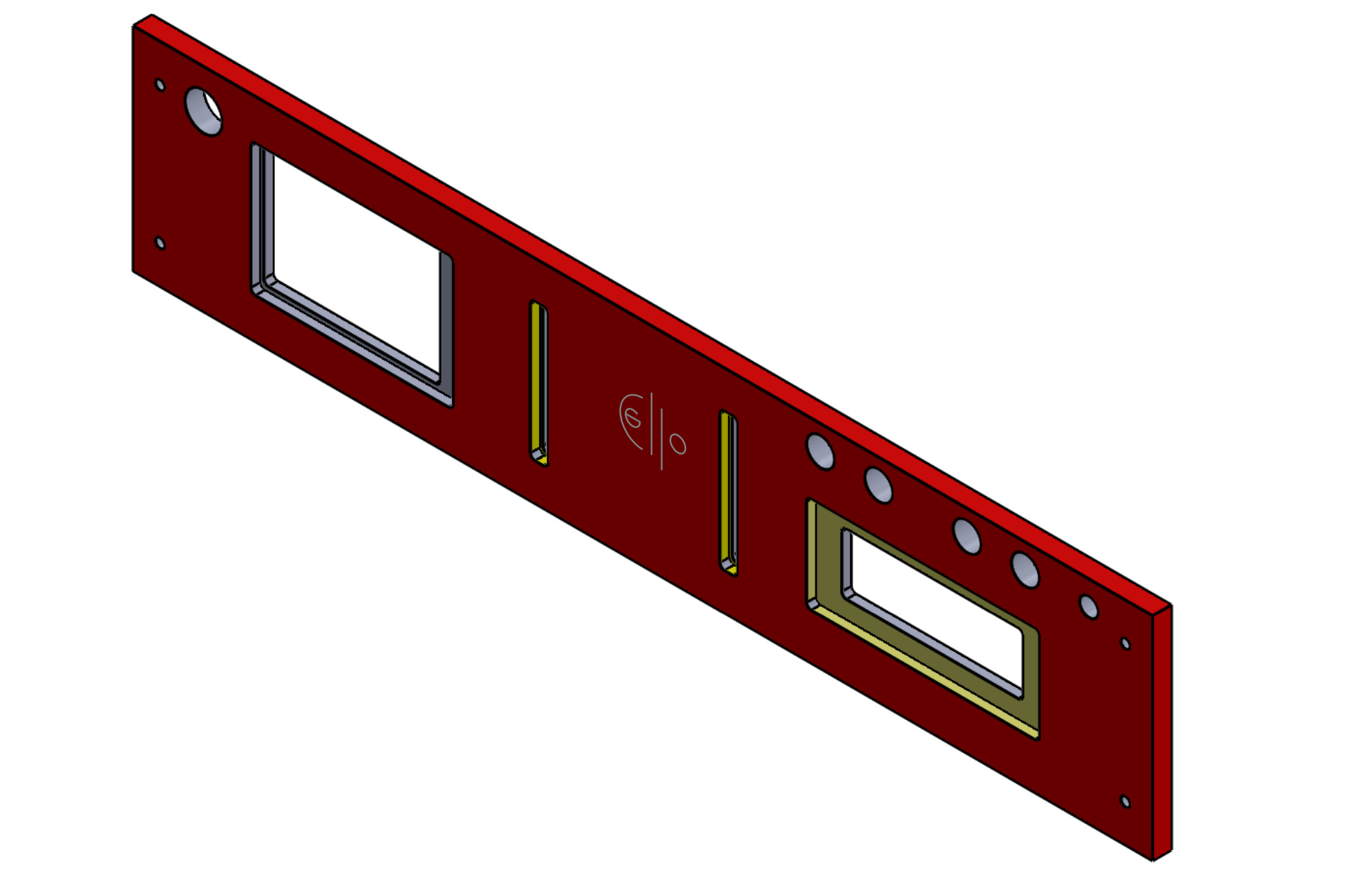
3 I only used word to draw a simple sketch . I went to some place to make the drills and they used my sketch to some pro cad application. if you want to use the same case I can post the full design file
Hi,
Thanks a lot,
It will help if you post the file, it will help me with the dimensions, how to arrange it on the paper then to chose the case. Now I am think it what to put on front, 3.5 display and vu meter or…
Thanks