inspired by many other DIY projects (especially thanks to Gerry_222 & mictester!) here is one picture of our “Huarez / DarkSign” project, named “HiFiPi” :mrgreen:
Although it is still work in progress (…need to add some small relay pcb to the second voltage converter exit which will supply dedicated power to the both USB ports at the front bezel of the MS-Tech CI-70 case…), everything is working flawlessly right now. If the still missing relay pcb is added soon, it will - in case of shutting down Volumio / Raspberry with the remote - cut the second stage power which supplies power to the usb ports only. As the RemotePi Board 2015 is powering down the Raspberry, the USB power supply also had to be switched down simultaneously, but this only is needed in this case because of the second 5volts stage which also supplies the Raspberry through the USB connector downside the pcb…
Equipped with the RemotePi Board 2015, not only Power On / Off could be done through any remote, also even more commands (…using LIRC - Thanks a lot Matt!) like Play, Pause, Skip Fwd / Back are possible !
Not finished yet completely, we´re already thinking in building another one, which will become even smaller due to the help of mictester (Thanks!!) suggesting a completely different way in building the power supply / converter
IMHO all of the DIY Volumio projects are one of the most interesting things to Audiophile / Electronics related people withing the last few months !
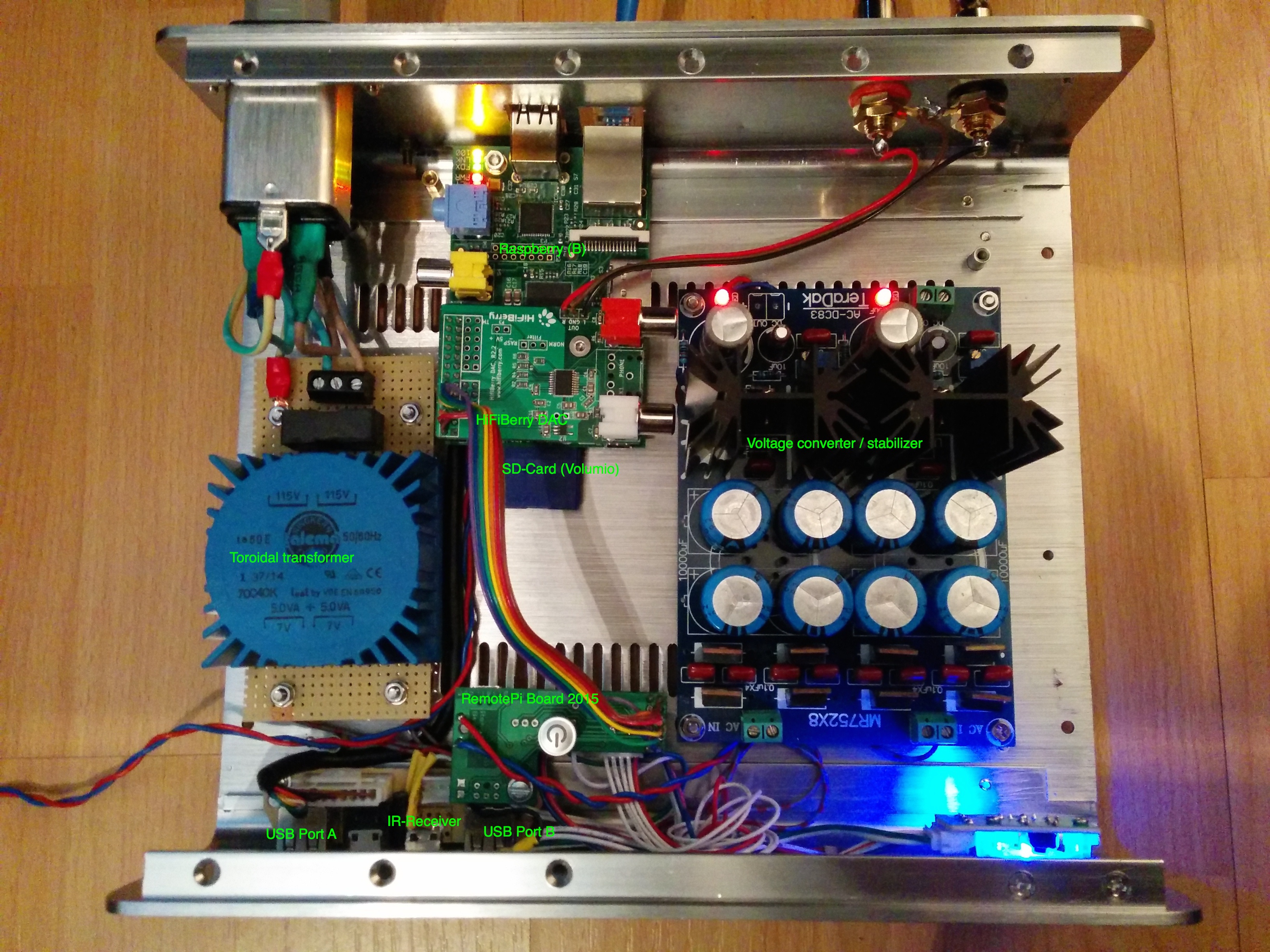
Toroidal transformer : RKPT 10207, Print, 10 VA, 2x 7 V, 714 mA and a 0,2A fuse in line from REICHELT Electronics
Voltage converter / stabilizer : Module d’ Alimentation linéaire régulé Double DC LT1083 20V 7.5A from audiophonics
Raspberry B and HiFiBerry (…here RCA-Version, you also could order it without soldered RCA connectors…)
RemotePi Board 2015 for comfortable steering using an remote (…normally the RemotePi Board itself will be mounted directly onto the Raspberry, here we connected the corresponding GPIO pins through a ribbon cable directly onto the HiFiBerry - for shure there a more “elegant” solutions…) The RemotePi Board 2015 directly is connected to one of the both regulated DC outputs, running at exactly 5.25V.
The TSOP38238 IR-Receiver which comes from the RemotePi Board 2015 is mounted directly behind the right 3.5mm jack, this seemed to be an excellent place for the receiver to work flawlessly with the remote out of any angle.
Furthermore, from downside the Raspberry´s pcb the two USB ports have been extended to use the two USB ports in the front panel of the MS-Tech CI-70. Speaking about the moderate power which comes from the USB-Ports, we not only extended the USB data lines (D+ / D-) from downside the Raspberry´s USB ports to the front - to supply more power to the USB the second DC output (also at 5.25V) is connected downside at the Raspberry´s USB pins to supply all four USB ports with enough power, for example if using an EDIMAX EW7811UN WiFi dongle together with e.g. someone´s mobile phone or USB stick which is connected at the front USB ports.
Please note: The second stage power supply is still work in progress and NOT to bee seen in the picture right now - the remaining space between the Raspberry and the RemotePi Board soon will be filled with a small pcb containing two relays which will be driven by either directly through the RemotePi Board´s GPIO pins so the RemotePi Board indirectly is shutting down the second stage USB power line simultaneously, or through the “WiringPi” GPIO access library for the BCM2835 - this could be used to switch any alternate (free) GPIO pin status like needed - at the moment we are trying out both versions…
Hello “augustohf” and “fotoflipao” - thanks for the replies, also many many thanks to “Gerry_222” (LG zurück!) for supplying / posting ´the basics´ of nearly all work shown here- no matter if people use some metal, wood, glass, paper or whatever case for their setup, the most important / interesting thing always is the main idea behind all this - creating a personally fitted, ´high end´ DAC / DAP which personally fits the environment in which it is driven…
Today the missing relay pcb has arrived, i will mount it withing the next days whilst time - if everything is “in place” i will post another photo and / or edit the thread to add a photo of the final “HiFiPi” version :mrgreen:
Nevertheless also BIG BIG THANKS to Michelangelo Guarise for making all this possible by creating such wonderful VOLUMIO stuff !!!
Lately I was googling arond for a " shutdown power buttton"-something and I also read and wathed the video about the Remoye PiBoard.
I see you have used the " extended" version of the board but is the Led in your powerbutton controlled by the board,? Becauase you are not using the origial button on the board and your button is turning blue and red.
I really like the board but I mis the option to " extend" the powerbutton or to connect my own button.
Yes, this is the “extended” version which originally comes with the IR-Receiver and a 2colour 5mm LED, both are connected through roundabout 20cm cables and a small connector which fits onto a pcb´s socket.
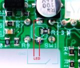
The original pushbutton is mounted / fixed onto the pcb, that´s right, but downside the pcb there are two pins where you can solder two cables and use any button you prefer within your setup, please take a look @ the image (Thnx Matt) for details. Also to be seen in the picture the two pins where to connect a third LED (in case)…
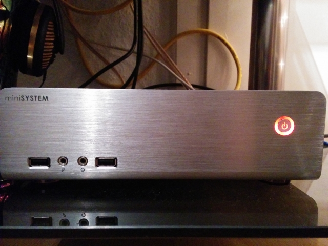
The blue LED (while booting VOLUMIO) and the red LED (shutting down) already had been included in the powerbutton´s pcb which comes pre-mounted withing the MS-Tech case i used for - i only replaced / reconnected the original 2colour 5mm LED (3pins) with the powerbuttons two separate LEDs…
I hope this is the information you are looking for
So you have used the signal for the " green" led to control your blue power-led?
You had to “hack” the board, thats a pitty because it should have been fully “external” with connectors/headers for the button, IR and ALL the leds.
Although I think it’s a great board I dont like the idea of paying 20 euro for a board and then heat up my soldering iron to modify it…
Indeed it is absolutely flawless to use the same GPIOs. As you please refer to the first photo, the coloured ribbon cable which comes from the RemotePi directly goes “on top” of the HiFiBerrys through-routed pins.
There is in no way any negative effect to the HiFiBerry as the main signals which are used are only for controlling the voltage supply for the Raspberry and to send the command to shut down / power up the Raspberry through the RemotePi. The GPIOs which are used for the digital music data are in no way affected
I wish you lots of fun whilst building your"rig" - please feel free to ask anything and - of course - please send a photo of work in progress / finished rig.
…in general you´re absolutely right - on the other hand speaking about soldering two cables whithin this thread which is part of a DIY-Forum isn´t that uncommon
Hello there… Your invention is really great - thank you a lot!! Good job! I was interesting in it a lot. And tried to make something like this too. I was searching for small relays pcb to the second voltage converter exit, as you said in the beggining of article. I found good one here hardware.nl/weidmuller as I needed to add some small relay pcb and now this hardware even supply dedicated power to the both USB too
thank you very much for pointing to the electronic parts supplier in NL They have lot´s of stuff there which perfectly could be used within Volumio DIY projects.
Another possible solution for powering up/down, extending AND controling the USB ports via simple script is this neat little device named “YEPKIT” which i stumbled upon some time ago:
BTW as you did in your desjn a high quality stable DC power supply is very important to a high end audio digital system.
I use a Hifiberry Amp+ on a rpi2. Since the Amp+ takes 12-18v input I just hooked up a AGM 12v sealed lead acid battery and put it also on a battery maintainer. Gives aa VERY stable DC voltage (thru chemistry) and give you an UPS at no additional cost.